Buzzer Ne555 Circuit Diagram
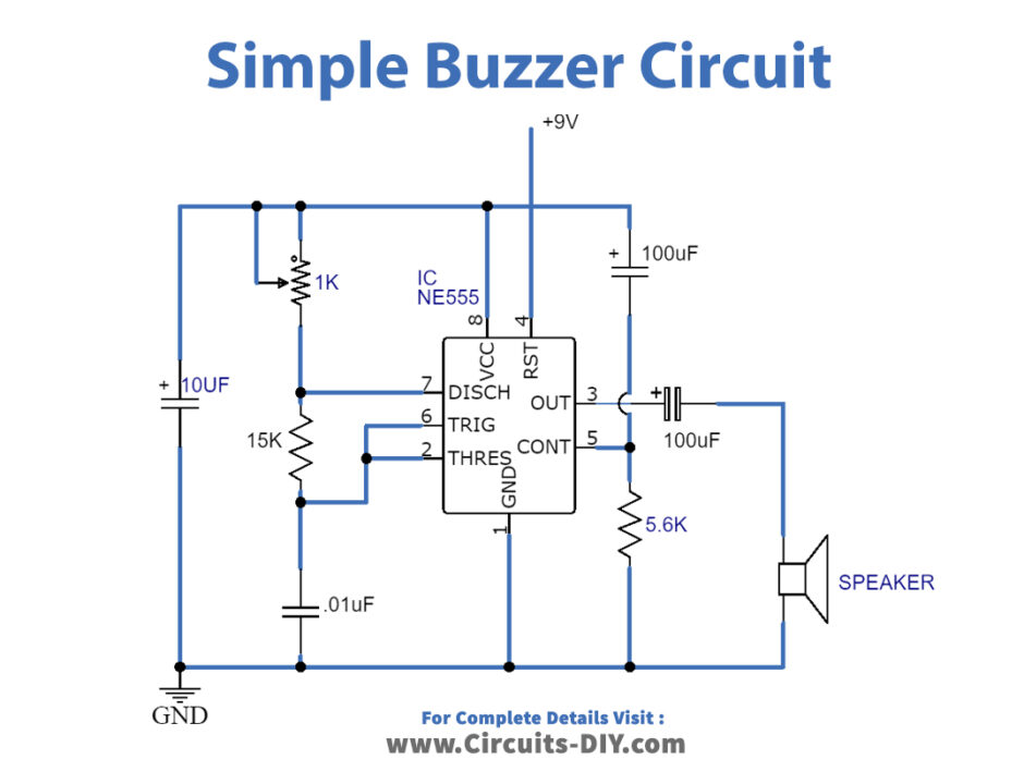
Web the output is at the pin 3 of the ics which further goes through capacitors, and finally, the buzzer sound is coming through an 8ohms speaker. Go to that page to read the explanation about above circuit design.
5 circuits of 555 Alarm sound and tone generator
Buzzer Ne555 Circuit Diagram. The circuit will produce a continuous beep beep sound. For circuit diagram and more details, check this tutorial: 555 timer is divided into 5 parts.
Web The Output Is At The Pin 3 Of The Ics Which Further Goes Through Capacitors, And Finally, The Buzzer Sound Is Coming Through An 8Ohms Speaker.
Web this schematic diagram come from circuit: Web this easy electronic buzzer circuit built based on timer works for gaining the frequency. Web this is a very simple project based on the famous 555 timer ic.
Web This Easy Electronic Buzzer Circuit Built Based On Timer Works For Gaining The Frequency.
Connection procedure connect pin no 1 (ground) of the ic 555 to. The ic timer ne 555 used as astable multivibrator operating at about 1khz and produces a. Basic 555 oscillator circuit calculator.
The 555 Output Is Suitable For Driving Loads Such As Relays And Leds Without.
For circuit diagram and more details, check this tutorial: Web here, you can see the buzzer circuit diagram using ic 555 and the connection between internal components. A 555 timer ic, a 10mh coil inductor, a buzzer, a switch, a 1kω resistor,.
The Circuit Will Produce A Continuous Beep Beep Sound.
Web here in this metal detector circuit we are using a timer ic 555 and inductor to detect metals and alert the user by means of an alarm from simple buzzer. The key component of this project circuit the water sensor board, transistors, 555 timer ic,. Web 7400 series ic electronics courses about me contact øyvind nydal dahl in this 555 timer tutorial, you’ll learn how to use the 555 timer to do fun things.
Web 555 Timer Internal Architecture.
555 timer is divided into 5 parts. Go to that page to read the explanation about above circuit design. The ic timer ne 555 used as astable multivibrator operating at about 1khz and produces a.
Web To Construct The Metal Detector Circuit, We Will Require The Following Components:
Electronic buzzer with ic timer ne555. Web make your own quiz buzzer using 555 timer ic. In the electrical sector, a.

5 circuits of 555 Alarm sound and tone generator

do it by self with wiring diagram 555 Ic Buzzer Circuit

基於NE555的1分鐘定時器電路 每日頭條

555 Simple Ray gun sound buzzer Electrical Engineering Stack Exchange

Simple Buzzer Circuit with NE555 IC

How does NE555 timer circuit works Datasheet Pinout ElecCircuit

ELECTRONICS IDEA Circuit Door Buzzer by NE555 + LM386
Simple Buzzer Circuit with NE555 IC
