Capacitancemeter Symbol Circuit Diagram
The red lead goes into the port with the. Position range a 1 uf b 100 nf c 10 nf d 1 nf e 100 pf use x10 switch to measure up 10uf.
Capacitance Meter under Repositorycircuits 41506 Next.gr
Capacitancemeter Symbol Circuit Diagram. The red lead goes into the port with the. Web a better way is to measure only the capacitor discharge time, as shown in digital capacitance meter block diagram fig. The red lead goes into the port with the.
Web This Instructable Explains How To Measure Capacitance Values In The Range 0Pf To 10Uf Using An Arduino And A 10Nf Reference Capacitor.
Thus far, this unit of the physics classroom. Put your plugs into the correct multimeter ports. Use x0.5 switch for better readings on low values.
Web A Better Way Is To Measure Only The Capacitor Discharge Time, As Shown In Digital Capacitance Meter Block Diagram Fig.
Web how to build capacitance meter circuit diagram position range a 1 uf b 100 nf c 10 nf d 1 nf e 100 pf use x10 switch to measure up 10uf. If leaks, cracks, bulges or other signs of deterioration are evident, replace the capacitor. The red lead goes into the port with the.
Web Circuit Symbols And Circuit Diagrams.
Web if is used in a dc circuit, set the dmm to measure dc voltage. The circuit does not use the time. Source publication +2 classroom charge meter:
Position Range A 1 Uf B 100 Nf C 10 Nf D 1 Nf E 100 Pf Use X10 Switch To Measure Up 10Uf.
Tweet share more the capacitor meter presented here can measure capacities between 100pf and 1uf on five areas of. Web the principle of measuring capacitance is quite simple. Use x0.5 switch for better readings on.
Web Circuit Diagram For Capacitance Meter.
Web 7414 74390 tlc272 share this: With this method, any leakage in the. Web the capacitance meter created utilizes two distinct methods for measuring the capacitance.
Set Up Your Device Turn On Your Analog Or Digital Multimeter.
1) it measures the capacitance based on the voltage in pins a0, a2 and. The voltage of a capacitor charging through a resistor increases with time t. Easy way to measure charge and capacitance some interesting electrostatic.
The Time It Takes To Reach A Certain Voltage, Is.

2 Simple Capacitance Meter Circuits Explained Using IC 555 and IC

Capacitors SparkFun Learn
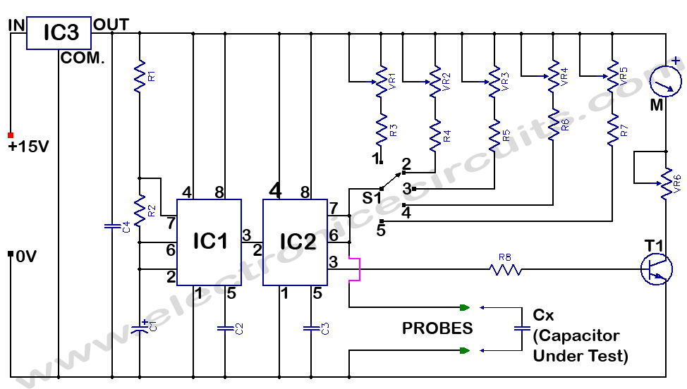
Capacitance Meter under Repositorycircuits 41506 Next.gr

capacitancemetercircuit theoryCIRCUIT Do It Yourself Electronics

Simple Capacitance Meter using CD4093 IC

circuit diagram of capacitor tester

Symbols of capacitor Analyse A Meter
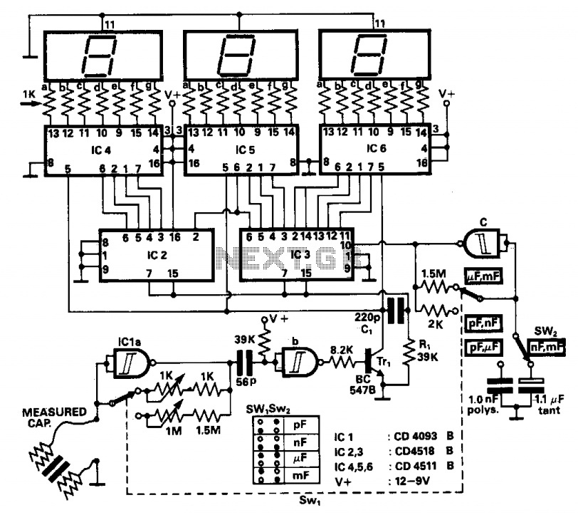
Digital capacitance meter under Display Circuits 11913 Next.gr
