Capacitance Measurement Circuit Diagram
If is used in a dc circuit, set the dmm to measure dc voltage. Web this effect can also be represented by a phasor diagram where in a purely capacitive circuit the voltage “lags” the current by 90 o.
Capacitance Measurement using Arduino
Capacitance Measurement Circuit Diagram. If is used in a dc circuit, set the dmm to measure dc voltage. Web the schematic diagram of capacitance measuring circuitis shown in fig. Operating principle figure 1 shows the operating principle for capacitance measurement based on the charge transfer method.
Operating Principle Figure 1 Shows The Operating Principle For Capacitance Measurement Based On The Charge Transfer Method.
So va minus vb, which is the voltage difference, that's essentially the electric potential energy difference divided by the charge. Web this effect can also be represented by a phasor diagram where in a purely capacitive circuit the voltage “lags” the current by 90 o. Web (8.2.1) 1 farad ≡ 1 coulomb / 1 volt or more generally, (8.2.2) c = q v where c is the capacitance in farads, q is the charge in coulombs, v is the voltage in volts.
Source Publication +12 Design Of An Instrument For Liquid.
Web schematic of the capacitance level sensor. When a capacitor is charged, electrons on the. Web 1 2 3 capacitors in d.c.
1) It Measures The Capacitance Based On The Voltage In Pins A0, A2.
Web the schematic diagram of capacitance measuring circuitis shown in fig. But by using the voltage as. | download scientific diagram schematic of the capacitance level sensor.
For Most Purposes And In Most Cases The Capacitor Must.
If is used in a dc circuit, set the dmm to measure dc voltage. Web a capacitive measurement circuit measures the impedance through an oscillating circuit. Web let's call that point b.
Since A Capacitor Is An Effective Break In A Circuit Within A Dc Environment, Charge Builds.
Web a capacitance meter is a piece of electronic test equipment used to measure capacitance, mainly of discrete capacitors. Circuits a capacitor is a gap in a circuit with space for charge on the 'plates' shown as the horizontal lines. Web the capacitance meter created utilizes two distinct methods for measuring the capacitance.
Web If The Capacitor Is Used In An Ac Circuit, Set The Multimeter To Measure Ac Voltage.
Web there are many advantages to using a capacitance measurement circuit diagram for electrical systems. These diagrams provide an easily accessible way to. It can be analyzed as a switched.
Web Reference Capacitance Charge And Discharge Measured Τ1=Rcref, Sensor Capacitance Charge And Discharge Measured Τ2=Rcsensor, According To The Internal.

Arduino Capacitance Meter Circuit Diagram and Code

DIFFERENTIAL_CAPACITANCE_MEASUREMENT_CIRCUIT Basic_Circuit Circuit

Simple Capacitance Meter using CD4093 IC

Measure capacitance with OPA604 and this circuit Valuable Tech Notes
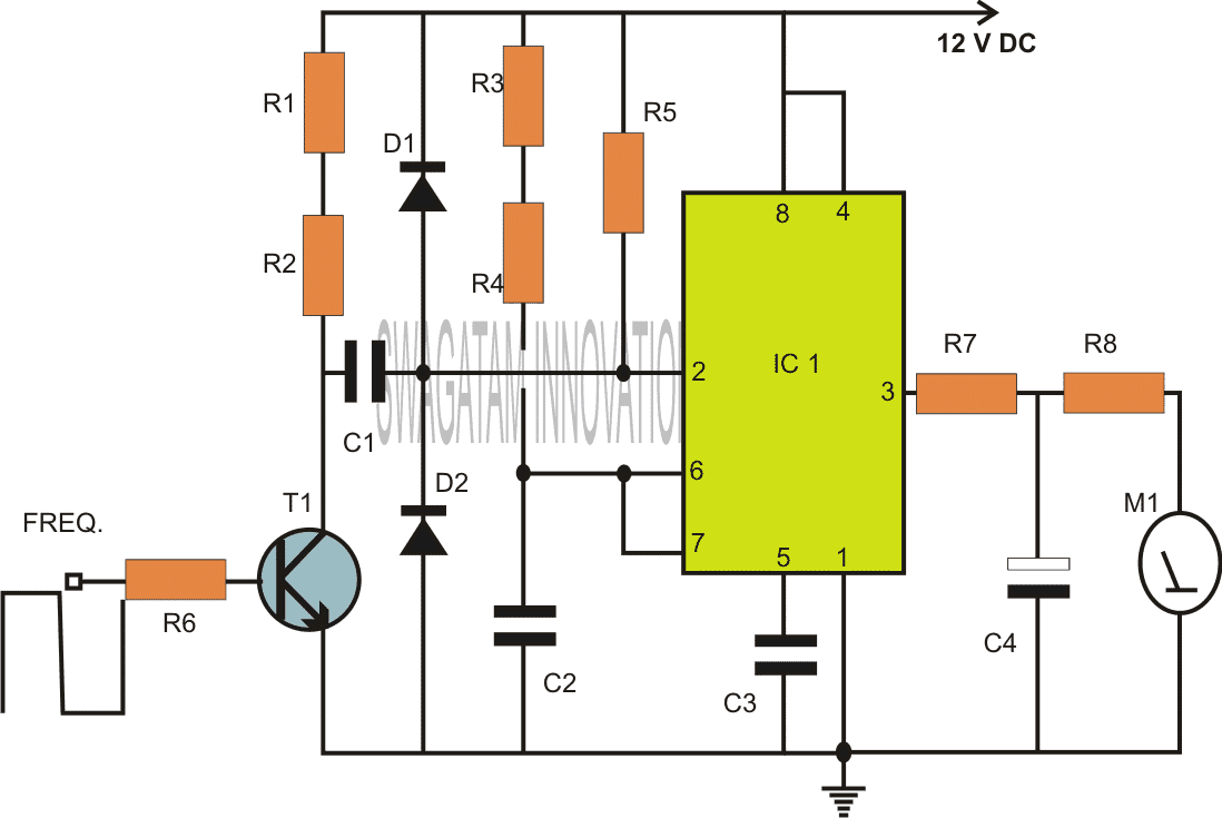
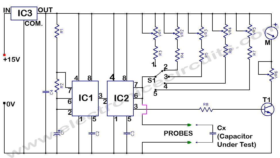
2 Simple Capacitance Meter Circuits Explained Using IC 555 and IC
Capacitance Meter under Repositorycircuits 41506 Next.gr

Capacitance Measurement using Arduino

Differential Capacitance Pressure Sensor Circuit
