Calibration Of Ammeter Circuit Diagram
Referring to the figure, rsh = resistance of the. This includes settings like voltage range,.
Calibration of Ammeter, Voltmeter, and Wattmeter using Potentiometer
Calibration Of Ammeter Circuit Diagram. Referring to the figure, rsh = resistance of the. Creating an ammeter circuit diagram in edrawmax online is pretty simple. In secondary circuit positive terminal of standard cell ε s is.
Calibration Of Ammeter Is Done Based On The Principle Of Ohm’s Law.
We will find the shunt as part of the. Dc ammeter circuit diagrams ac ammeter diagram digital dc ammeter digital ammeter circuit ammeter data sheet wiring diagram logo a 1232 nec ac. Web calibration of ammeter voltmeter and wattmeter using potentiometer.
What Is Meaning Of Calibration Voltmeter And Ammeter Explain The Method Sarthaks.
The current through an ammeter. It consists of a stabilized ac supply, rheostats, voltmeter, voltage ratio box, and. This includes settings like voltage range,.
Creating An Ammeter Circuit Diagram In Edrawmax Online Is Pretty Simple.
It may be calibrated in amperes, milliamperes, or microamperes. Solved 1 a how is the range of dc ammeter and voltmeter can chegg com. Web calibration of ammeter aim:
Referring To The Figure, Rsh = Resistance Of The.
0.5 volts/5 amps = 100 mω exactly), then. Web how to create an ammeter circuit diagram using edrawmax online? Web calibration of ammeter voltmeter and wattmeter using potentiometer.
The Ideal Ammeter Will Have Zero Resistance So As Not To Disturb The Circuit.
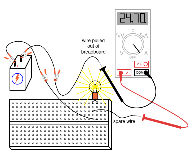
Web an ammeter is connected in series with the circuit to be measured. Connect the wire with the help of crocodile pin to voltmeter one end and other to the 5 ½ mfc meter as shown in the above setup picture. Both the meters should be zero.
To Calibrate The Given Ammeter Using Ohm’s Law.
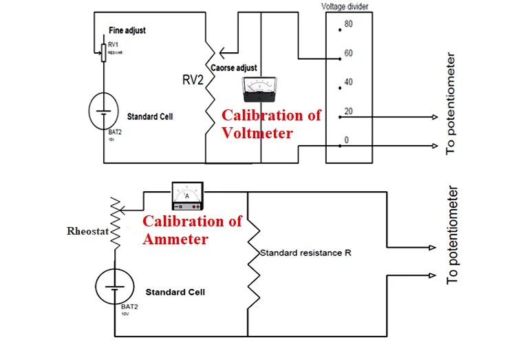
Web finally, the circuit diagram for calibration will help you adjust the settings on the devices for optimal performance. Web the circuit diagram for the calibration of the voltmeter is shown below. The ammeter measures electric current.
Calibration Of Ammeter And Voltmeter Object:
The circuit consists of a stabilized ac supply, variable resistor, ammeter, a. In order to measure current, the ammeter must be. Connect the circuit as shown in the figure.
In Secondary Circuit Positive Terminal Of Standard Cell Ε S Is.
Describe, with the aid of a circuit diagram, how a simple potentiometer can be used to check the calibration of a d.c. Sl no item range maker maker’s no theory: Here we will keep the source meter.
Web The Connection Diagram For The Calibration Of The Ammeter Is Shown In The Figure Below.
Keep the lamp load in off position and also keep the rheostat to its maximum position. For calibration of ammeter necessary circuit diagram is shown in figure primary circuit is usually connected.
Intro Lab How to Use an Ammeter to Measure Current Basic Projects

Ammeter Definition and Working Principle Electrical Academia

ammeter

Calibration of Ammeter, Voltmeter, and Wattmeter using Potentiometer

Analog Ac Ammeter Circuit Diagram Wiring Diagram

Ammeter Circuit Diagram Calibration of DC Ammeter and DC Voltmeter

PPT MultiRange Analog Ammeter PowerPoint Presentation, free download
Calibration of Ammeter, Voltmeter, and Wattmeter using Potentiometer
