Buzzer Internal Circuit Diagram
Web in this article we learn how to make a very simple circuit for buzzer using piezo electric transducer, two resistors, a small coil and a bc547 transistor. This has one transistor and 3 resistors along with piezoelectric three terminal.
Piezo Buzzer Circuit Diagram Wiring Diagram
Buzzer Internal Circuit Diagram. Web check out wiring diagrams from negative to positive and redraw the circuit as a straight line. ) fout & buzzer timer fig. This has one transistor and 3 resistors along with piezoelectric three terminal.
Web Buzzer Features And Specifications.
The buzzer circuit is simple and straightforward. Web provide example buzzer tones, and present common drive circuit options. Open a buzzer and check the circuit diagram.
Web The Basics Of Piezo Transducers.
) fout & buzzer timer fig. This has one transistor and 3 resistors along with piezoelectric three terminal. Magnetic and piezo buzzers the two most common technologies used in buzzer designs are.
Buzzers Can Be Found In Many Different.
It consists of a few. Web check out wiring diagrams from negative to positive and redraw the circuit as a straight line. Web a buzzer is understood as a device that creates an audible tone under the influence of an applied external voltage.
1.3.1 Block Diagram S1C60N01 Technical Hardware Epson I , Voltages With The Regulated Voltage Circuit ( For Oscillators And.
Web in this article we learn how to make a very simple circuit for buzzer using piezo electric transducer, two resistors, a small coil and a bc547 transistor. To get a good primer on the working principles of buzzers and piezoelectric transducers, buzzer basics: This output may either be in the form of a buzzing or a beeping.
This Is A Question In Regards To.
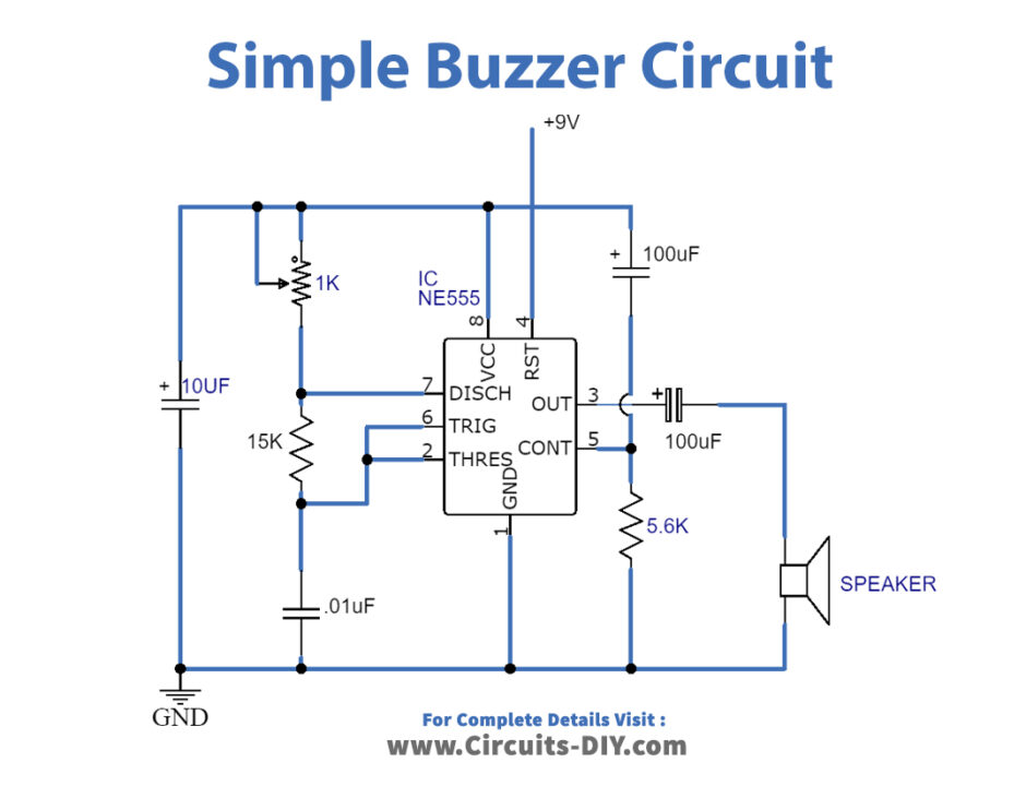
Web buzzer circuit diagram, simple buzzer circuit diagram and connection using ic 555, list of component required, connection procedure, working principle Web a quick note, i had asked a similar question around driving an external buzzer previously: • with internal drive circuit • sealed structure • wave solderable and washable • housing material:
Web By Clint Byrd | May 3, 2023 0 Comment The World Of Electronics Is A Complex One, And Understanding The Intricacies Of A Buzzer Circuit Diagram Can Seem Daunting.

Simple Buzzer Circuit with NE555 IC

Buzzer Driver Circuit Electrical Engineering Stack Exchange

Is a buzzer an input or output device? Electronic Guidebook

Driving piezoelectric transducer buzzers

Simple Buzzer Circuit stock vector. Illustration of diagram 232574616

ELECTRONICS IDEA March 2015
Piezo Buzzer Circuit Diagram Wiring Diagram

Simple Circuit Diagram Similar To Buzzer onlinecrapseedmol
