Buzzer Circuit Diagram Working
Web the one shown here is a simple buzzer which when powered will make a continuous beeeeeeppp. A visual representation of the circuit can.
Buzzer Driver Circuit
Buzzer Circuit Diagram Working. This electric current is then used to. This is a useful feature for troubleshooting. Open a buzzer and check the circuit diagram.
Open A Buzzer And Check The Circuit Diagram.
So i have made a circuit diagram in which when the first buzzer is pressed,. Sound, the other type is called a readymade buzzer which. Web parts list r1 = 100k, r2 = 4k7, t1 = bc547, l1 = buzzer inductor, pz1 = piezo element, 27mm, three terminal rubber ring = 22mm simple buzzer using 8 ohm.
The Working Principle Of The Buzzer Circuit Buzzers Are Sound Devices That Can Convert Audio Signals Into Sound Signals.
Web with normal buzzers, it sometimes becomes difficult to tell that which team pressed the switch first. Web hence, the buttons work only after resetting the entire circuit. The buzzer is controlled using npn transistor bc547 whose control signal is the common trigger to.
Web For Example, If A Circuit Is Open, The Buzzer Will Be Triggered And Will Remain Inactivated Until The Circuit Is Closed.
It consists of a few basic. Web how to make a water clock what is a buzzer circuit? A visual representation of the circuit can.
The Buzzer Circuit Is Simple And Straightforward.
This is a useful feature for troubleshooting. Web the one shown here is a simple buzzer which when powered will make a continuous beeeeeeppp. This electric current is then used to.
Web Hi , This Video Is To Show You How To Make A Simple Beeping Buzzer Circuit, Which Can Be Used As Alarm.
When the armature is brought or. Web the schematic diagram of the buzzer can give you an indication of the different components needed in the circuit. This has one transistor and 3 resistors along with piezoelectric three terminal.
Web A Buzzer Circuit Diagram Shows How Electric Current Is Controlled Through A Series Of Switches By An Electromagnetic Coil.
In this process, we would use an armature as a key (secondary) in the circuit we have.

How to Make buzzer circuit projects Circuit
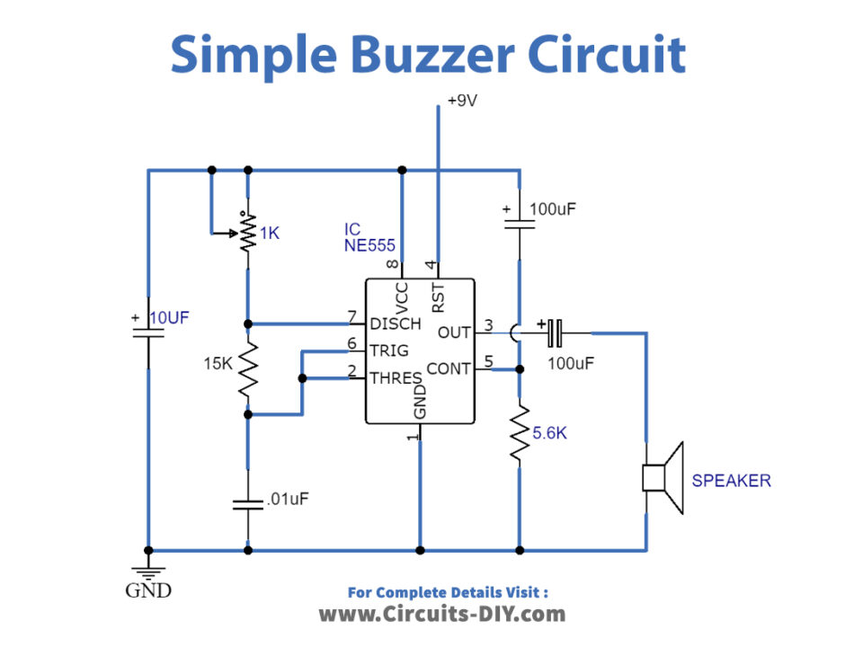
Simple Buzzer Circuit with NE555 IC

Driving piezoelectric transducer buzzers

Can a buzzer function as a switch in a circuit? Electronic Guidebook

Simple Circuit Diagram Similar To Buzzer onlinecrapseedmol

Is a buzzer an input or output device? Electronic Guidebook

Buzzer Driver Circuit

Simple Buzzer Circuit with NE555 IC
