Brake Chopper Circuit Diagram
Web installation instructions dynamic brake or chopper connection (1336 plus, plus ii, force, impact g & h frame drives) this publication will provide connection and drive. 104148244, v1.1, 08/2017 7 ª s i e m e n s a g 2 0 1 7 a l l r i g h t s r e s e r v e d 1.2.2 description of the core.
Solved How to enhance the protection of S12ZVM’s VLS_OUT NXP
Brake Chopper Circuit Diagram. This monitoring is necessary because power surges can occur in the intermediate circuit. Web for regenerative braking and motoring these type of chopper configuration is used. Web schema of braking circuit (a) topology of braking chopper in 3 lvl npc inverter, (b) switching function for chopper transistors.
104148244, V1.1, 08/2017 7 ª S I E M E N S A G 2 0 1 7 A L L R I G H T S R E S E R V E D 1.2.2 Description Of The Core.
Web installation instructions dynamic brake or chopper connection (1336 plus, plus ii, force, impact g & h frame drives) this publication will provide connection and drive. Technical data, dimension drawings, example circuit. This monitoring is necessary because power surges can occur in the intermediate circuit.
Web A Standard 12V Linear Voltage Regulator (78L12, Ic1) Is Used For Generating Supply Voltage For The Op (Lm358, Ic2) And Via R5 / R6 Resistor Voltage Divider Reference Voltage (Approx.
Web difference between brake chopper and brake resistor the difference between the brake chopper and brake resistor includes the following. Web a brake chopper is used to monitor the dc link voltage in a frequency inverter. A chopper is a device that converts.
Electrical Engineering Questions And Answers.
Web oct 2017 elshiekh mohammedsaeed ke jia abstract—pv system integration with power grid has many challenges. Web schema of braking circuit (a) topology of braking chopper in 3 lvl npc inverter, (b) switching function for chopper transistors. Source publication application of a non.
What Is The Type Of.
Web motor modules as braking chopper entry id: Below is a simple example wiring diagram and a description of the functionality. What is the function of brake chopper , draw the circuit diagram?
Web • Dimension Drawings Contains The Dimension Drawings Of The Brake Chopper Module, As Well As The Standard Brake Resistors And Cooling Fans.
Similar to the transformers of the ac circuit, choppers are used to step up and step down the dc power. Web whenever the voltage in the drive’s common dc bus exceeds a certain limit, a braking chopper connects the bus to a braking resistor. Web in electronics, a chopper circuit is any of numerous types of electronic switching devices and circuits used in power control and signal applications.
Web For Regenerative Braking And Motoring These Type Of Chopper Configuration Is Used.
One of these challenges, the disconnection of pv inverters. Power range 70 to 714 kw. Web main supply if the chopper remains conductive in a fault situation.

Patent US5117166 Chopper circuit for dynamic braking in an electric

Brake Chopper circuit. Download Scientific Diagram

Solved How to enhance the protection of S12ZVM’s VLS_OUT NXP

VFD Regen Diodes and the Brake Chopper Circuit YouTube

Braking and Regeneration iKnow Knowledge Base Invertek Drives
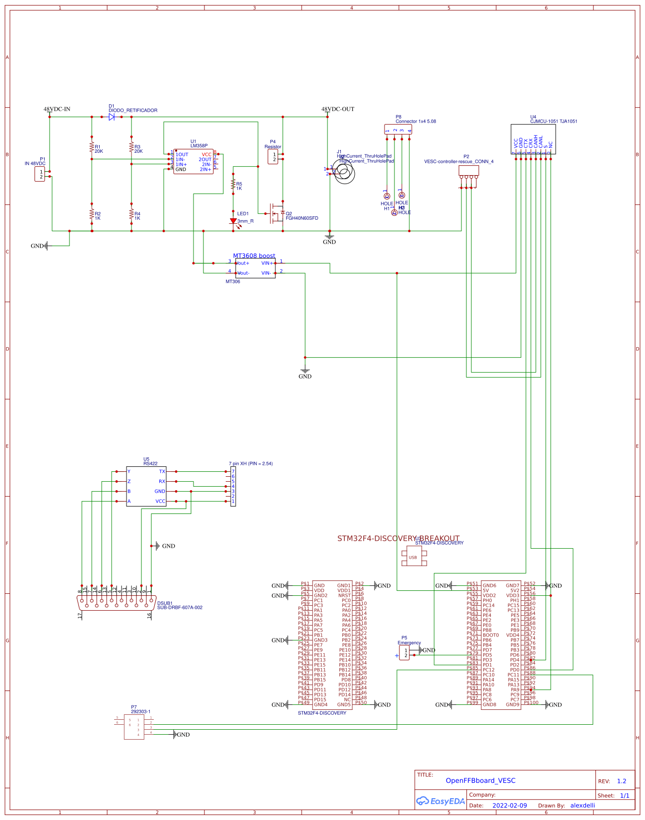
OpenFFB for VESC circuit BissC EasyEDA open source hardware lab

Brake chopper circuits in VFDs KEB

Brake Chopper Trinamic
