Bootstrap Circuit Diagram
As the name suggests, the converter takes an input voltage and. Web how does a bootstrap gate driving circuit work?
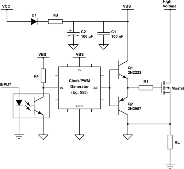
gate driving Bootstrap circuit for highside MOSFET driver
Bootstrap Circuit Diagram. Web download scientific diagram | circuit diagram of a boost converter to an inverter connected to the network [4]. Web download scientific diagram | circuit diagram of a boost converter to an inverter connected to the network [4]. Web the circuit diagram in figure 1 describes the bootstrap operation.
Web The Circuit Diagram In Figure 1 Describes The Bootstrap Operation.
Web the typical schematic of the bootstrap circuit is presented in figure 1. Dc bus voltage control for pv sources in a dc distribution system. As the name suggests, the converter takes an input voltage and.
| Bootstrapping, Cmos And Circuits |.
Bootstrap circuit r d1 f cboot vcc vboot vbo high side gate driver low side gate driver vcc. Web how does a bootstrap gate driving circuit work? Web bootstrap circuit consists of a bootstrap diode(bsd), a bootstrap capacitor(bsc) and a current limiting resistor.
Web The Proposed Circuit Is Made Up Of Cmos Transmission Gate (Tg) Switch And Two New Bootstrap Circuits For Each Transistor In Tg.
Bootstrap mosfet gate driver technique foolish engineer 34.9k subscribers subscribe 682 28k views 9 months. Web download scientific diagram | circuit diagram of a boost converter to an inverter connected to the network [4].

How does a Bootstrap gate driving circuit work? Bootstrap MOSFET gate
gate driving Bootstrap circuit for highside MOSFET driver

Bypassing Sync Driver Bootstrap for 100 duty Electronics Forum

Figure 1 from A Bootstrap circuit for DCDC converters with a wide

Driving High Side MOSFET using Bootstrap Circuitry (Part 17/17)

Electronic Bootstrap circuit function Valuable Tech Notes

Bootstrap Amplifier Circuit using Transistors

Conventional bootstrap switch. (a) Circuit schematic. (b) Cross section
